Home » Plan a trip » Suzuki V-Strom DL650 Valve Check and Adjustment
Suzuki V-Strom DL650 Valve Check and Adjustment
Valve check and Adjustment for Suzuki V-Strom DL650.
The bike I’m working on is a 2016 DL650AL2 with 20,153km on the clock, but the process is basically the same on all DL650’s, plus the Suzuki SV650 series and Gladius models, there are some minor variations on each but nothing major.
I usually check the valve clearances at around 20 – 25,000km and normally find them on the tight side. My preference is to adjust them to the middle of the tolerance ie 0.15mm (0.006inch) inlet and 0.25mm (0.010 inch) exhaust.
I know some people prefer to set clearances on the outer limits but I’ve never found this necessary as once set they don’t seem to move again for many, many miles – my current personal DL650 has not needed the valves adjusting again in over 95,000km after the initial adjustment at 25,000km.
Preparation for valve check and adjustment
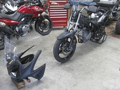
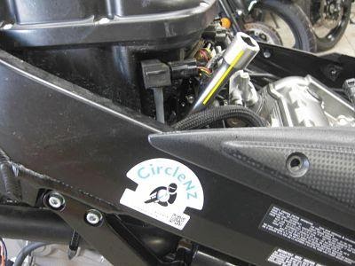
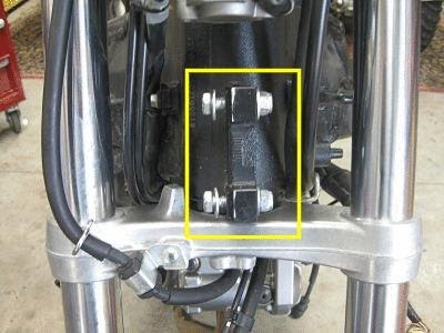
Remove the seat, fuel tank side covers, lift and remove fuel tank. To make access much easier I also remove the entire front end ‘cockpit’ in one lump (not necessary on the earlier Generation 1 models).
Once you’ve got the tank and side panels off there are only two bolts and three electrical connectors securing the cockpit so better to spend another ten minutes removing the whole thing as it really makes the job much easier.
Once that’s done drain the radiator, disconnect the fan and horn, and remove, I also unbolt the radiator reservoir under the seat and swing it out of the way. There is no need to drain the engine oil. I’m not going to give step by step instructions on the above, some of it you’ll find in the owners manual, otherwise Mr Google will help you out.
Once you’ve got to that stage here’s what you should have.
Part 1 - Check the valve clearances.
First we’ll check the valve clearances to see if any adjustment is necessary.
TIP – go slowly and methodically, think about each step, this is not a job you can rush, photographing the process as you go is a good way of keeping a record. I usually start with the front cylinder.
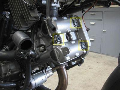
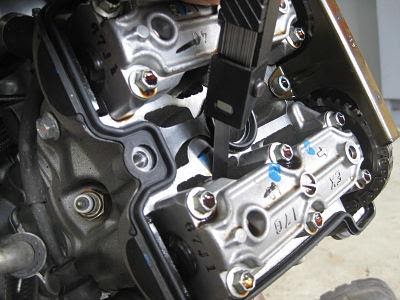
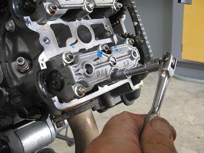
1. Remove the rocker covers (3 hexagonal bolts on each) – a light tap with a mallet helps break the gasket seal.
2. Remove spark plugs – if you’re going to replace them remove all four, if not one per cylinder is fine.
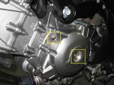
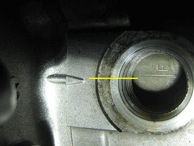
3. Remove the two covers on the left side of the crankcase, the lower one allows the crank to be rotated, the upper one gives access to the crank timing marks.
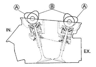
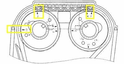
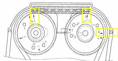
4. Use a 17mm socket to rotate the crank anticlockwise until the ‘F’ mark in the upper inspection hole aligns with the mark on the crankcase. Your looking to find Top Dead Centre (TDC) on the compression stroke so make sure both cam lobes on the front cylinder are in Position A (see diagram below), if they’re not, rotate the crank another 360 degrees until it’s correct, this is important – YOU MUST MEASURE THE CLEARANCE WITH THE CAMS IN THE CORRECT POSITION.
To recap, use a 17mm socket to turn the crank anticlockwise until;
The ‘F’ mark aligns correctly in the inspection window and;
The cam lobes for the front cylinder are in position ‘A’ (if they’re not you’ll need to rotate the crank a further 360 degrees until they are).
The camshafts are now in the correct position to measure the front cylinder valve clearances.
5. Insert a feeler gauge and measure each of the four valve clearances, it’s a pretty fiddly job, I have a set of gauges which I’ve bent at the ends to make the job easier. You’re looking for the thickest gauge which will fit the gap – a nice sliding fit without any undue amount of drag is what you’re trying to find.
6. Once you’ve taken the measurements for the front cylinder valves ROTATE THE CRANK 270 DEGREES ANTICLOCKWISEuntil the ‘R’ mark appears in the inspection hole, check that the cam lobes for the rear cylinder are in the ‘B’ position (see diagram above). Now measure the clearances for the rear cylinder valves.
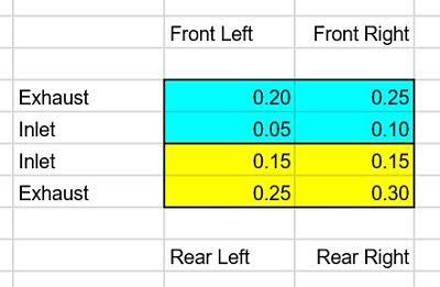
As you measure the clearances write them down, I make a chart as if I am sitting on the bike looking down onto the top of the engine, that makes sense to me but use whichever method works for you. All of my measurements are recorded in mm.
Now that we know the clearances it’s a simple job to work out which valves, if any, need adjusting.
The inlet valve gap should be between 0.10 – 0.20mm (0.004 – 0.008 inch), the exhaust valve 0.20 – 0.30mm (0.008 -0.012 inch), if they’re within this range there’s no need to go any further, just reassemble everything in the reverse order and check them again in another 30,000km or so.
In my case I need to make some adjustments, I prefer to set all clearances in the middle of the recommended range so I’ll need to adjust four out of the eight valves (front left ex, front left in, front right in, rear right ex) as these four are either out of spec or right at the extreme limit.
NOTE – I know some people prefer to set on the outer limits but I’ve never found this necessary. The DL650 seems very easy on it’s valves, once set they don’t seem to move again for many, many miles.
Now we know some adjustment is needed it’s time to move on to the next stage.
Part 2. Valve clearance adjustment.
I suggest you read, and re-read this section before you do any work on the bike, it’s essential that you have an understanding of what you’re actually doing, if you get it wrong and stuff up the valve timing you can do catastrophic damage to the engine. If you don’t rush and take the time to think things through you’re unlikely to have a problem.
I start with the front cylinder and do one cam at a time.
1. Rotate the crank until the ‘F’ mark aligns and the cam lobes are in position ‘A’ (just the same as when checking the front cylinder clearances in Part 1).
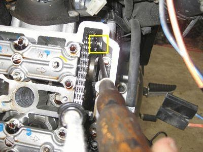
2. Remove the camchain guard.
NOTE – it’s worth photographing the position of the cams at this point, the ‘1F’ mark on the exhaust cam should now align with the surface of the cylinder head, also note the count of sixteen cam chain rollers between the ‘2’ mark on the exhaust cam and ‘3’ mark on the inlet cam, you must make sure the cams are positioned exactly like this on reassembly.
A few photos taken now may help sort out any problems later.
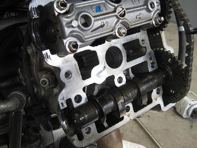
This is how the front cams should look (viewed from left of the bike).
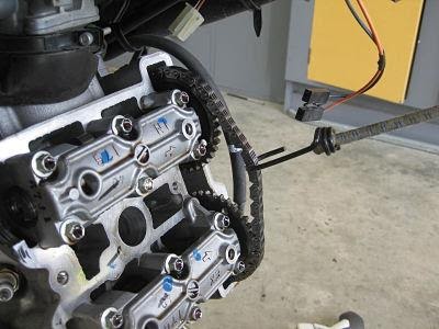
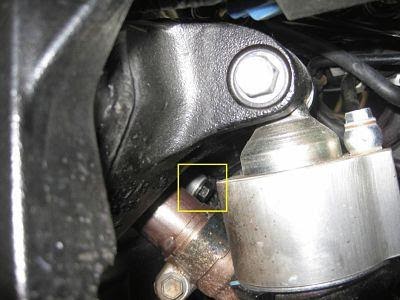
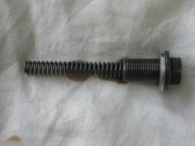
3. Now you have to take tension off the cam chain in order to get enough slack in the chain to remove the cams. This can be done by removing the 12mm nut on the back of the camchain tensioner allowing the tensioner spring to pop out. Then use a thin flat edge screwdriver to release the ratchet on the actual adjuster mechanism. This sounds harder and more complicated that it is – hopefully the photos help explain this.
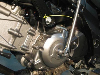
The front tensioner is easy to get to, it’s on the rear of the cylinder below the air filter, I used a 12mm socket on a long extension – leave the tensioner nut sitting on top of it’s spring and washer along with the socket, that way it’s much easier to re assemble.
Next use a narrow flat blade screwdriver to push down on the small tab to release the ratchet mechanism, it’s much easier than it sounds.
I use a bungee to keep some tension on the chain – it stops the chain falling off its drive way down inside the crank and keeps it located on the cam teeth.
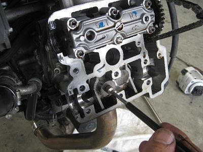
4. Now slacken the six bolts on the exhaust cam chain journal.
5. Remove the cam journal bolts and remove the journal, it’s on dowels so takes a little gentle wiggling to free it up.
6. Remove the exhaust cam. Again this is a little fiddly but the tension from the bungee helps keep the cam chain in position on the inlet cam. Once the cam is removed use a small magnet to remove the shim bucket, make sure to place the magnet in the center of the bucket so that the shim comes out with it. Note to self, next time take a photo of the can bucket and shim!!
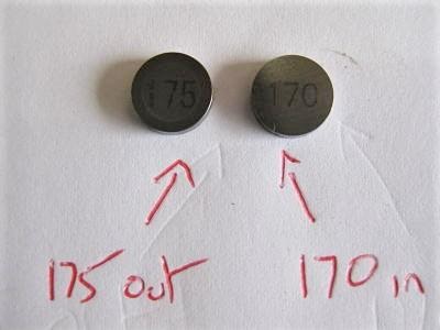
7. Now it’s simply a matter or reading the number on the shim and replacing it with one of the correct thickness. Suzuki do provide a chart in their Service Manuals which help with this but a simple micrometer and common sense is all that’s really required. My chart shows the front left exhaust to be 0.20mm, I’d like to set it at 0.25 therefore I remove the 175 (1.75mm) shim and replace with a 170 (1.70mm). Simple eh?
A word on shim sizes. They are usually marked ‘120’, ‘125’, ‘130’ etc, right up to around ‘220’. 120 is a shim thickness of 1.2mm, a 125 is 1.25mm etc, so if your exhaust valve clearance is right on the minimum at 0.20mm (0.008 inch) and you’ve removed a 175 shim, replacing it with a thinner 170 will increase the clearance by 0.05mm (0.002 inch) putting you right in the middle of the recommended clearance at 0.25mm (0.010 inch).
IMPORTANT- check the shim sizes before use, just because they say they are a certain size doesn’t mean they are – measure them.
8. Place the new shim number side up on top of the valve (it sits in a little recess), give it a drop of oil, then replace the shim bucket. Repeat for the other exhaust valve.
9. Replace the camshaft making sure to align up the 1F mark on the cam with the cylinder head correctly, I also check that I have the correct count of 16 rollers between marks ‘2’ on the exhaust cam and ‘3’ on the inlet cam, this is why I do one cam at a time.
I know that I’m about to remove the inlet cam but I’m trying to ensure everything is correct at each stage. Put a little oil on the cam journal bearing surfaces and replace it, lightly bolt into place.
10. Repeat Steps 5 – 9 the above for the inlet cam making sure to replace the cam with 16 rollers between the ‘2’ and ‘3’ marks on the cam.
11. Tighten and torque the journal bolts on both cams (10N/m) and replace the cam chain tensioner nut/spring to put pressure back on the chain, but do not replace the cam chain guard at this stage.
That’s the front cylinder done, now it’s on to the rear. This next bit is important and often seems to confuse.
12. TURN THE CRANK 360 DEGREES ANTICLOCKWISE UNTIL THE ‘F’ MARK APPEARS IN THE INSPECTION HOLE AGAIN – this may sound a little counter intuitive but it’s the correct procedure. The ‘1R’ mark on the rear cylinder inlet cam should now be aligned with the flat cylinder head surface. Take a photo.
This is how the rear cams should look (viewed from right of the bike), note that the cam lobes are in a different position to when you measured the clearances.
13. Now repeat Part 2, Steps 2 – 11 however;
A couple of things to watch out for while working on the rear cylinder. The rear cam chain tensioner is a real PITA to get to. It’s on the rear of the rear cylinder and well hidden.
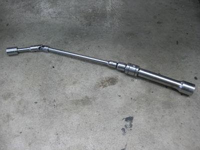
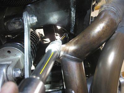
The best approach I’ve found is from underneath the bike in front of the swinging arm to the right of the exhaust downpipe. Use a 12m socket and long extension with a swivel joint, a combination of 1/4, 3/8 and 1/2 drive bars seems to work best. They say a picture is worth a thousand words so:
The rear tensioner is not easy to get to, here it is viewed from the left side of the bike.
Here’s the tool I use on the rear tensioner, a combination of 1/4 and 1/2 inch sockets with a flexible joint.
Here’s the tool in situ going up from underneath the bike just in front of the swinging arm and to the right of the exhaust downpipe. Awkward but not impossible.
When removing the rear tensioner, the nut, washer and tensioner spring will fall out, don’t loose them and make sure they all go back in on reassembly.
Adjusting the rear clearances is just a repeat of the fronts, by now you should be feeling pretty confident. Once both cylinders are done turn the crank over several times (to squeeze excess oil from the shims), check the clearances again (you did measure those shims didn’t you?) and again check that the timing marks are correct.
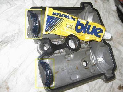
If all is well replace the camchain guard, clean the mating surfaces and replace the rocker head covers (14N/m for the hex bolts). I’ve always re-used the original gasket putting just a little sealer (Hylomar) around just the half moon shaped section, none have ever leaked.
That’s pretty well it. While it can sound like a daunting job it’s really not too difficult, you’ll probably spend more time stripping the bike down than actually making any changes.
Now is a good time to replace the plugs and air filter then reinstall the radiator, fuel tank, fairing etc and you’re good to go.
A few things worth noting.
CHECK/MEASURE the clearances using the crank ‘F’ mark for the front cylinder and ‘R’ mark for the rear cylinder.
ADJUST the clearances using the crank ‘F’ mark for both but with a 360 degree crank rotation between each cylinder.
Cylinder head cover bolts 14N/m
Cam journal bolts 10N/m
Spark plugs 11N/m
Wrapping up.
I make a little chart showing what size shims I have installed for each valve, this makes it easier if you have to adjust anything next time around (which you probably won’t). I also record the sizes of the shims which haven’t been altered, just so I know what’s in there, no need for a picture of the chart, it’s just a repeat of the one used to record the clearances.
One last thing, if you’ve removed the cockpit consider replacing the bolts with longer ones and add a nylock nut too, they have been known to work loose.
Like this article, why not share it or post a link to this page?